|
Mercedes Diesel Valve Adjustment Procedure |
| Home |
| Bio diesel and WVO page |
All parts used in these pictorials are available at the diesel parts for sale page
Mercedes Diesel Valve Adjustment Procedure
One of the most overlooked maintenance procedures besides fluid and filters, has to
be the valve adjustment. Mercedes recommends this simple procedure every 12k miles
or one year. I can't tell you how many older Mercedes diesels I see that desperately need
the valves adjusted. It is not hard to do even for the beginner. There are a couple of
special wrenches, feeler gauge and new valve cover gasket that is needed. One car in
particular that I have done the valves on, went from a rough running sled, to smooth
as a Cadillac just because of the valve adjustment. This pictorial is the for the
do-it-yourselfer, so follow along and lets adjust some valves..........
Safety and security tips:
Please remember to recycle all your used fluids at an appropriate recycling center. Be mindful to not spill or splash fluids on yourself, others or the ground. Also as a safety tip please remember anytime you are working on, around or under your car, to wear safety glasses and secure the car with wheel stops and approved jack stands!
This job needs to be done with the engine COLD. Meaning it has sat overnight and not run.
Now your engine may look a little different than this one. This happens to be a 617
Non-turbo model. But this procedure is the same for the 4cyl or 5cyl diesel engine.
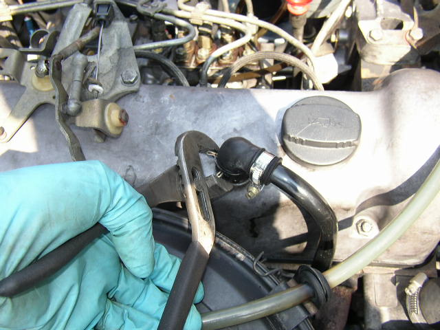
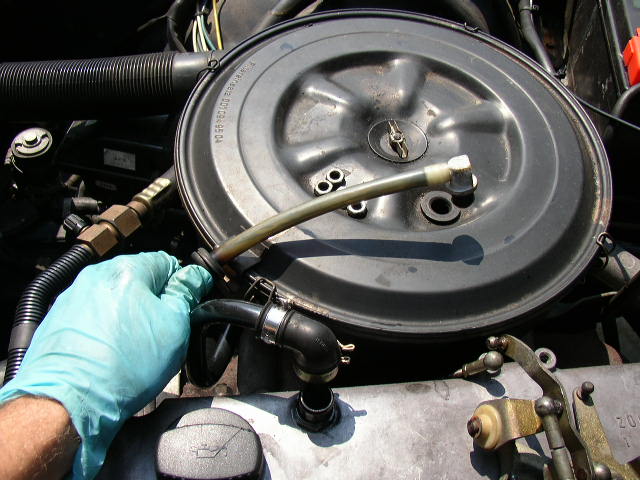
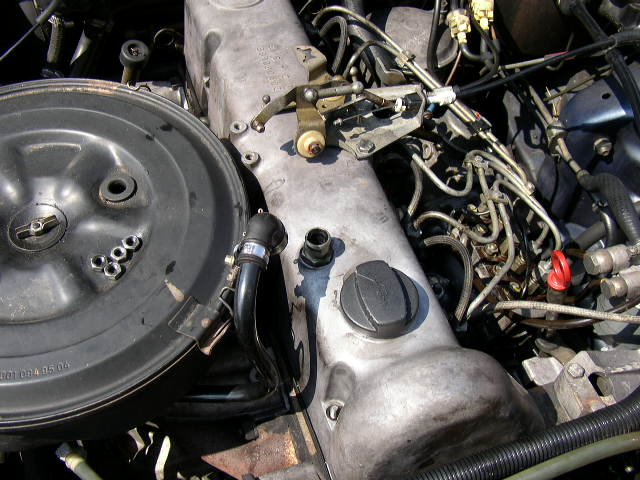
Start by removing the breather hose on the valve cover. The turbo model will have a
little different configuration that mounts in the air cleaner.
Look at your throttle linkage very closely. Make a drawing or take some digital pics,
but don't start just taking stuff apart. I like to remove the MINIMUM amount of linkage
to ease installation and headaches. Remember the less you take apart, the easier the
job will be. ***Neat trick*** Before you just snap the linkage apart, take some silicone
or WD-40 spray and spray into the joint. Over time and probably due to a lack of proper
lubrication, the little half spring will get sticky and hard to remove and can break.
The spray helps to give the spring some lube to move in its grove, and allow the ball to
come out without breaking the spring.
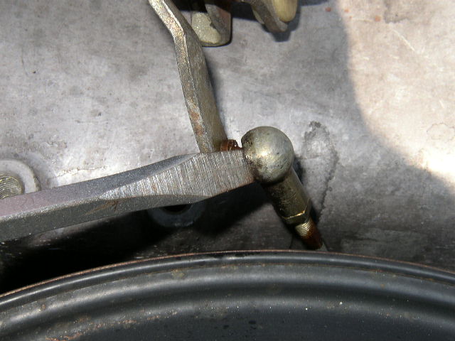
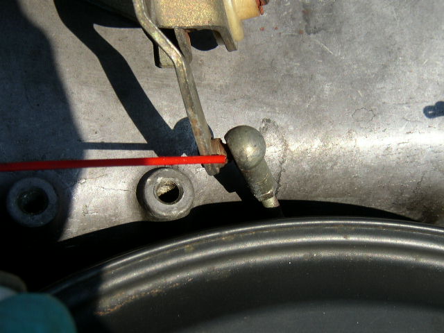
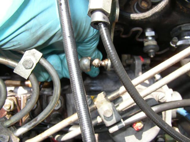
After spraying I gently use a flat blade screwdriver, and pop the joint apart. Please
don't force the socket or it will break. Don't ask me how I know that:(
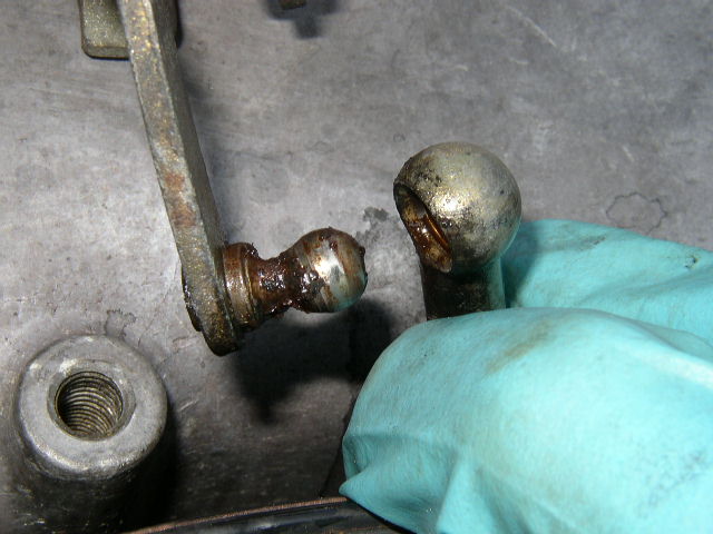
This is the joint after is comes apart. Clean and re-grease before re-assembly.
Remove the joint where it connects to the injection pump. If you have a turbo diesel,
then also remove the joint at the cruise control actuator.
For all you turbo diesel owners, you probably see the linkage is a different set-up on the
non-turbo engine. Not to worry! Just look at your particular linkage, and remove the
minimum you have to. Also loosen the four valve cover nuts with your 13mm socket.
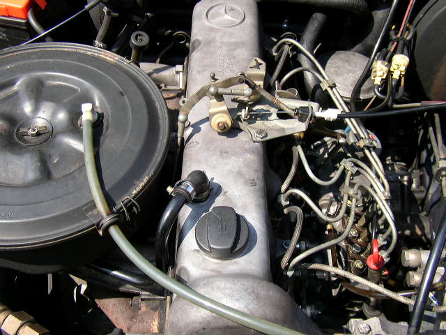
***Trick*** When I am doing this job, I will remove just enough linkage to free the valve
cover. All the linkage in the pic on the valve cover, just stays there including the cables.
When the valve cover is removed I just lay it over on its back on the fender, with all the
stuff still bolted to the valve cover. Makes it MUCH easier!
For the non-turbo types take the hose loose form the air cleaner to for extra room
when the valve cover is removed.
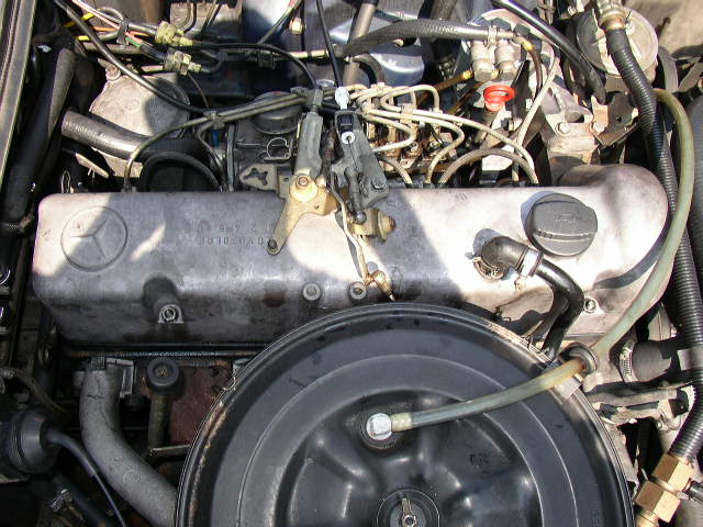
After the nuts are removed, I just lift the valve cover up and lay it on the drivers fender.
All the linkage and the two cables that you saw in the earlier pics, is still bolted to the valve
cover on the top.
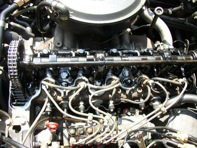
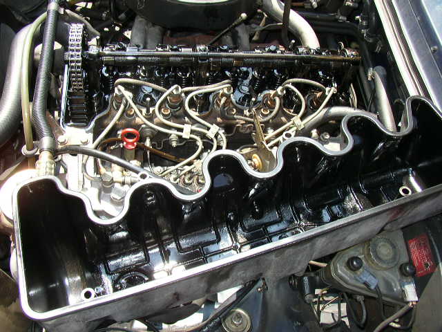
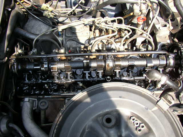
Naked exposed upper cylinder head.
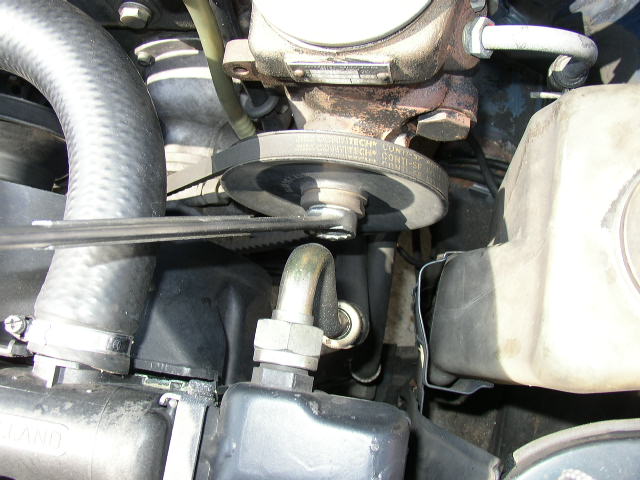
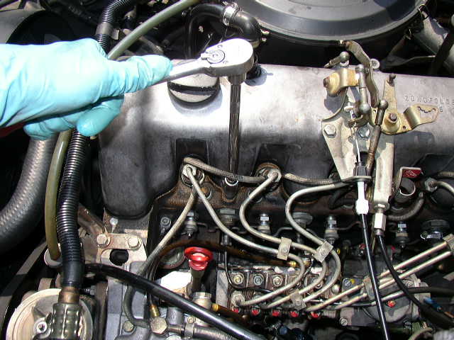
If you have ever tried to turn the engine over by the crankshaft bolt, you know it is almost
impossible to get to with the fan etc. on. Use your 22mm wrench and turn the engine by the
power steering pump bolt. Yes you need to make sure you belt is tight to specs.
***Always turn clockwise, never counter clockwise!
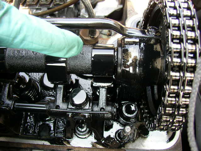
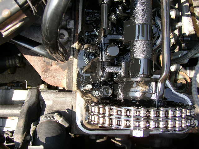
Get the number 1 cyl camshaft lobe pointing straight up, 90 degrees relative to the adjusting pad just like shown in the picture. To your eye this will look like the lobe is in about the 1 o'clock position. Never try to adjust the valve with the lobe in any other position than pointing this way.
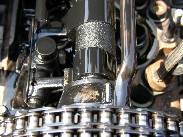
Another shot of the lob position.
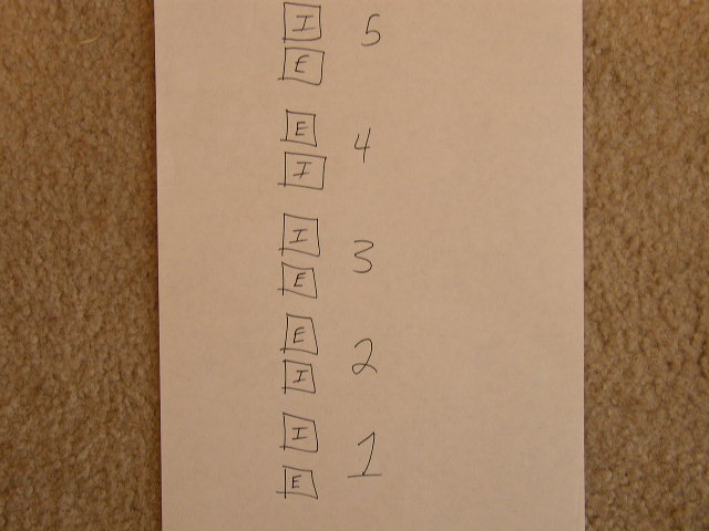
Now there may some confusion as to which valve is the intake and exhaust. On the 4cyl
and 5cyl diesels, the very first valve is the exhaust. You can tell by looking straight over to
the passenger side of the engine and see if it is directly lined up at the exhaust or intake
manifold. I make a sheet just like this, before every valve adjustment. So I know which
valve is which and gives me a visual to "check off" the ones I have completed. For the
its just one less thing I have to remember. Download the valve adjustment sheet here 5 cylinder sheet 4 cylinder sheet
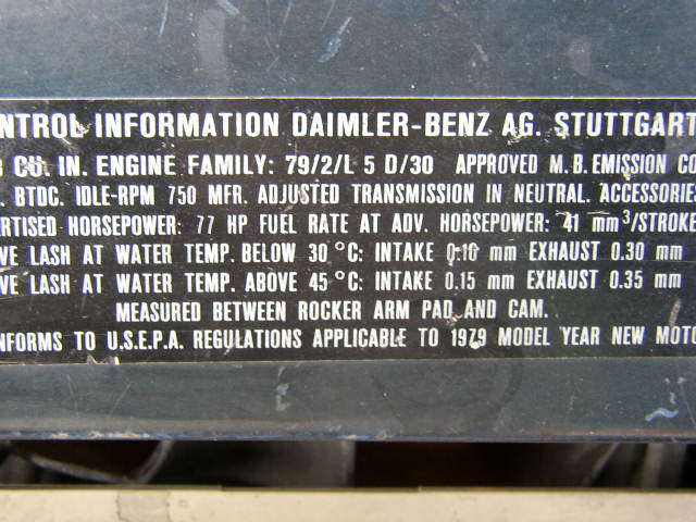
The specs for the adjustment are on the core support for your model. All the NON turbo 4cyl and 5cyl diesels use (.10mm or .004 inches) intake and (.30mm or .012 inches) exhaust. The turbo models use (.10mm or .004 inches) intake and (.35mm or .014 inches) exhaust.
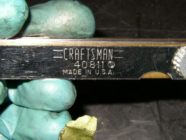
Make sure your feeler gauge will have the correct specs to do the valves. I have two sets
of feeler gauges and only one has the correct sizes. Not all feeler gauges have the "fine"
sizes. As always I use Craftsman when ever possible.
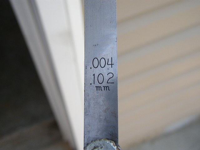
I know what you are going to say, "hey its .102mm not .10mm" Yes I know but the difference
is insignificant. I have never seen a .10mm feeler lead. I am sure they are out there but remember
this country is just in its metric infancy.
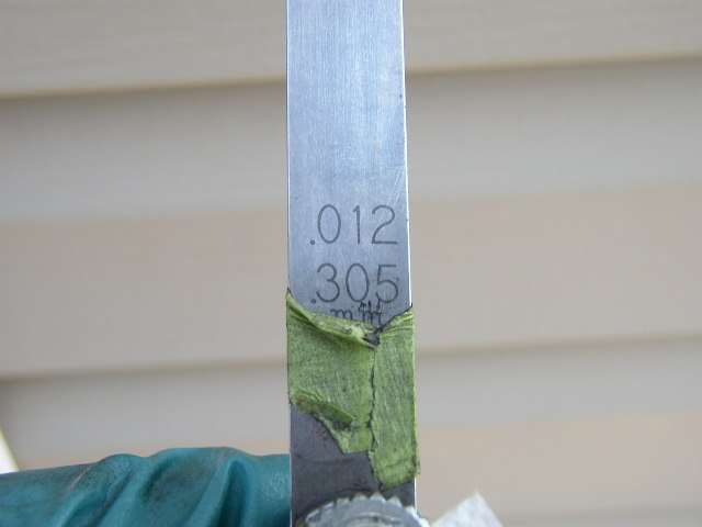
Same deal with the exhaust as the intake. I use a piece of tape to mark the exhaust so
I can find it quickly when doing the valves.
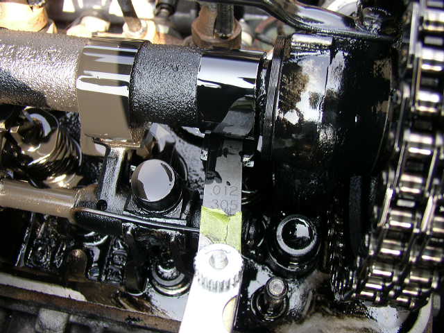
This is how to check the clearance. Between the camshaft lobe and the rocker arm pad.
There should be a very little resistance when the feeler gauge is slid between. Remember
if you are going to err, err on the side of too loose rather than too tight. If its been a while
since you have done the valves, then they will probably ALL be very tight. I have done cars
that I could not get the feeler gauge between ANY of the lobes. They were WAY too tight and
long overdue for and adjustment.
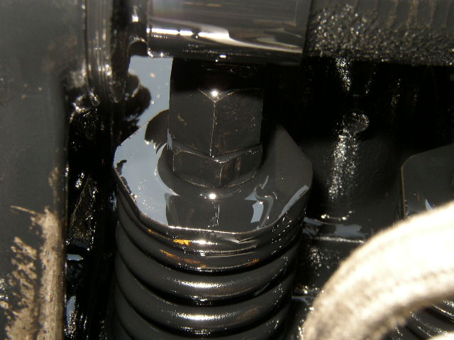
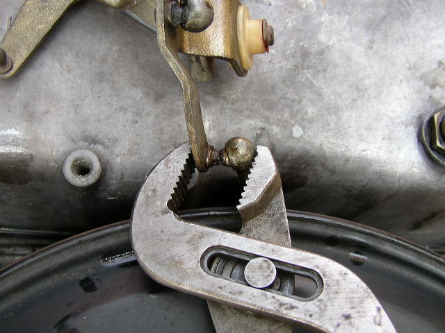
Here is the two nut that you will be working with. The top nut it the adjusting nut, the bottom
is the lock nut.
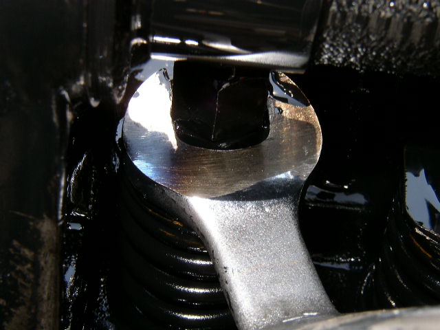
Valve adjusting wrench is on the lower lock nut ready to take tension off the top adjusting nut.
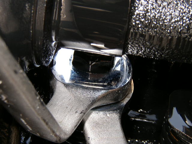
Bottom nut is being loosened while holding the top nut still. Once the bottom nut is loosened
then you can turn the top adjusting nut clockwise to increase the clearance or counterclockwise to decrease
then recheck with your feeler gauge. If the clearance is good, then lock the bottom nut back against the top nut,
while holding the top nut still. It takes a little practice, but as you do it you will develop a "feel" for it.
After that valve is adjusted just rotate the engine until the next camshaft lobe points straight up. As you
do the adjustment, mark off on your sheet so you know which valve has been done.
NOTE I actually do the
adjustment opposite from how I am showing you on the pictorial. I use the bottom nut as the adjusting nut and the
top nut as the locking nut. It works equally well in either instance since both methods will accomplish the same
thing. But in reviewing the Mercedes manual pics I wanted to show you the factory way..
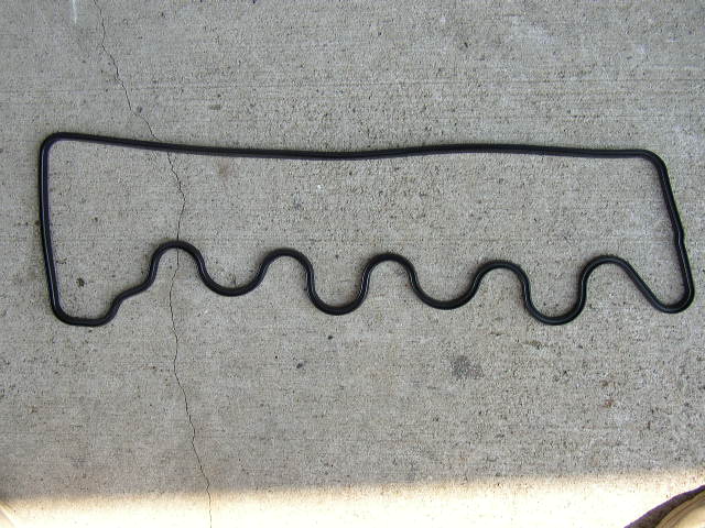
New valve cover gasket. Always replace the gasket when you adjust the valves. If you
don't then you will have a nice oil leak.
Valve cover back on and ready to be bolted down.
When re-assembling the linkage, be gentle. Most of the time you can just squeeze the socket
together with your fingers. Use some pliers if it is a little stiff.
All back together and ready for smooth sailing.